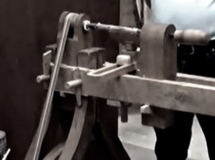
Of all the tools in the armory of the production engineer undoubtedly the lathe in its many forms is the most important.

It is also probably the oldest, since elementary forms of the lathe appear to have been in use from the 14th century onward.
The Pole Lathe
The pole lathe was used very early on to turn chair legs and other similar parts, and was often found actually in the woods from whence the raw material was drawn, because an essential ingredient in the construction or make-up of the pole lathe, namely a strong, springy sapling, was available on the spot.
It will be appreciated that work, mounted between centers, and driven by means of a cord wound around it, does not revolve continuously but moves backwards and forwards; forwards when the operative presses down the treadle lever and backwards when he releases it to allow the sapling to reverse the motion and return the treadle to its original position ready for the next working stroke.
With indoor versions of the pole lathe, similarly to that in the illustration, the sapling was replaced by a bow fixed to the ceiling of the workshop.
Inevitably, the discontinuous rotation of the work inseparably from the arrangement became intolerable and some means of improving matters had to be sought.
The Wheel Lathe
These resulted in the introduction of the wheel lathe, an example belonging to John Smeaton of lighthouse fame.
The Wheel Lathe needed two men to operate it, one to provide the motive power the other to do the actual turning operations.
In early lathes, initially, the work was mounted between dead centers, that is a pair of centers neither of which rotate.
A pulley was attached directly to the work, and the driving belt was often crossed to avoid slip.
A further development in the driving arrangements removed the pulley attached directly to the work and transferred it to one of the dead centers upon which it ran.
The work itself being driven by a pin fixed to the pulley through the medium of a carrier.
Smeaton’s Lathe
The further and final development provided the lathe with one live mandrel carrying the driving pulley, this last arrangement permitting work other than that set between centers to be mounted on the live mandrel itself.
In common with similar lathes at the time Smeaton’s lathe was constructed mainly of wood, but by the end of the 18th century iron and other metals began to be generally used in the manufacture of lathes.
Consequently their capacity increased so that it was not uncommon for two men to be employed for turning the driving wheel.
The Verschoyle Mandrel
Shortly after the First World War had ended in 1918 a device called the Verschoyle mandrel was put on the market.
This little machine bore a strong likeness to the wheel lathe having inherited its greatest drawback in that two men were needed for its successful working.
It was said that it could be used by a single operative; but turning the mandrel with one hand and endeavoring to guide a turning tool with the other must have been a pretty exasperating experience.
At all events the device was not a success and soon went off the market.
Back to the Wheel Lathe
But to return to the original wheel lathe.
Its drawbacks soon led to the demand for a tool that could be worked by one man alone and this led to the introduction of the Treadle Lathe.
Here as will be seen, the treadle is connected, through a pitman, with a crankshaft supported usually on centers fitted to the stand carrying the lathe bed itself.
The driving pulley consists of a heavy iron flywheel provided with grooves to accommodate a round catgut or leather belt used to transmit power to the mandrel.
Whilst both the headstock and tailstock appear to be iron castings supporting the mandrels normally associated with them, it is not certain that the particular lathe illustrated has a cast-iron bed and legs.
It some instances these components were still made of wood.
At this stage it is as well for the readers to acquaint themselves with the salient parts of the lathe and the names given to them.
The Treadle Lathe
Among the designs left by that genius Leonardo da Vinci were those for a treadle lathe.
As with many of his suggestions there is no certainty that this lathe was ever constructed.
Had it been made it is possible that the lathe as a practical machine tool would have developed earlier than it did.
Be that as it may, the main impetus in development came from the clock-makers in the 18th century who needed machines that would produce the many intricate parts they required.
In this way the lathe became a ‘do-all’ capable of not only turning but gear-cutting as well.
At the same time the requirement for ornamental work led to the introduction of the rose engine and other ornamental turning lathes and devices.
Screw-Turning Lathes
The screw, because of its many applications, is probably the most important of the mechanical elements.
It is said to have been invented by Ardeytas of Tarentum, a Pythagorean philosopher and mathematician, about 400 B.C., but is generally associated with Archimedes who died in 212 B.C.
Both Hero and Pliny have described wooden screws as having been applied to presses in the first century A.D., but do not appear to have left a description of how these screws were made.
On the other hand, Leonardo da Vinci has again left us with a machine design in which two leadscrews geared to the workshaft enabled the pitch of the screws being cut to be varied at will by changing the ratio between the driving and the driven gears.
In this matter da Vinci’s machine bears a strong resemblance to a device used in Woolwich Dockyard about 1850.
But in his design the leadscrews did not control individual toolposts, but acted together to advance a single toolpost spanning the whole machine.
Leonardo da Vinci has recorded the use of the screw both in the making of other screws and the construction of machines, but whether or not his screw-making machines were ever made seems uncertain.
Nevertheless, in this matter he was clearly capable of very original thought so, as he was demonstrably much in advance of his time, it seems that he owed little of this to his contemporaries.
The production of screw threads had evidently been exercising the minds of mechanics for a long while, but it was not till about 1700 that a practical solution to the problem presented itself.
By this time the design of the lathe headstock had advanced to the point that would allow the device to be put into practice.
The Traversing Mandrel
This device, introduced about 1700, consisted briefly in allowing the lathe mandrel to slide axially in its bearings under the control of a so that components having short lengths of thread could be produced.
Examples of these lathes were installed in a large works where the author was once employed, and there was a complete kit of equipment for use with them.
But not much use was made of the traversing mandrel device, the operatives and planners preferring to use other methods with which they were more familiar for the batch production of screwed components.
The traversing mandrel was evidently well known to clock-makers and ornamental turners in the late 17th century, for the description of an ornamental lathe having the device at that time exists.
This machine has two forms of tailstock, one apparently able to be set over so that tapers could be turned.
The limitations of the traversing mandrel soon became apparent, so it was not long before many first-class brains turned their attention to alternative methods of screw thread production.
Thus the names of such eminent people as Henry Maudslay, David Wilkinson in America, Richard Roberts, James Nasmyth and by no means least, Joseph Whitworth, were concentrating on this problem and others connected with the improvement of the lathe as a practical machine tool.
For screwcutting purposes, the traversing mandrel was superseded by the leadscrew.
This is a long screw running the full length of the lathe bed and usually in front of it, though some lathes locate them differently.
The leadscrew can be driven from the mandrel through a train of gears that may be changed at will.
A nut attached to the saddle of the lathe engages the leadscrew, so, when the screw rotates the saddle will travel along the lathe bed.
The ratio of the gearing that connects the mandrel and leadscrew together dictates the pitch of the screw that will be cut.
For example if the mandrel itself turns at twice the speed of the leadscrew then the pitch of the thread cut on the work will be twice that of the leadscrew itself whatever that may be.
Small lathes of the type usually have leadscrews with a thread pitch of ~ in. so, when the mandrel makes two turns for each one of the leadscrew, the thread pitch cut will be it in.
Using the principle of which this example is the basis, it will be understood that, by selecting gears to connect the mandrel and leadscrew in the right ratio, a wide range of thread pitches can be cut in the lathe.
Lathe Innovators
Henry Maudslay, 1771-1831, was employed originally by Bramah, the ‘locksmith’, but left his services in 1797 following a dispute over rates of pay.
Bramah himself was a prolific inventor, numbering among his designs the hydraulic press and the beer engine, but there is little doubt that he owed much to Maudslay, as a practical mechanic, who perfected Bramah’s locks.
Maudslay also produced a machine for winding springs and which set him to consider the problem of screw cutting.
The end of the century saw the production of two further lathes equipped to produce screw threads; one by a Frenchman named Senot, the other by David Wilkinson, an American, who introduced his machine in 1798.
It is at this point that the name of Richard Roberts 1789-1869 becomes important.
He had originally been employed by Maudslay, from whom he must undoubtedly have absorbed some sound engineering practice, but in 1814 he left him and set up on his own in Manchester.
His claim to fame rests on his introduction, in 1817, of the first practical back-geared headstock to be applied to a lathe.
