Here’s a detailed explanation of how mechanical pendulum clocks work.
The Basics
Clockworks are made up of a collection of gears (called wheels in clock parlance) that convert the power of a wound spring or weight into a uniform motion.
These wheels are attached to slender rods called pivots, which ride in holes drilled in the clock plates.
Most pivots will also have a pinion mounted on them as well. The pinion is another gear, much smaller in diameter than the wheel, and with far fewer teeth.
The pinion will engage a wheel on a different pivot, thus transferring the power to the next wheel. This combination of wheels and pinions driving each other is called a train
Even though all gears in the movement are connected to each other, it is helpful to think of them as three distinct trains based on what they do:
- The Power train is responsible for transferring the power of the spring or weight to the timekeeping train.
- The Timekeeping or Going train is responsible for turning the cannon pinion exactly once per hour. This drives the minute hand of the clock.
- The Motion train is responsible for converting 12 rotations of the cannon pinion into one rotation of the hour wheel. This drives the hour hand of the clock.
Each of these trains will be discussed in detail in the sections below.
Energy Sources: Weight-Driven and Wind-Up Clocks
Before we get to the detailed explanation of the gear workings of mechanical clocks, let’s briefly look at common power sources.
How do Weight-Driven Clocks Work?
Weight-driven clocks use the gravitational pull of a weight for power.
A primary weight is lifted with a counter-weight as a store of energy. Then the gravitation pull on the primary weight powers the gears in the clock.
Here’s a great video demonstration of their workings:
In early weight-drive clocks, a verge and foliot escapement regulated the rate at which the gear train ran.
In the verge and foliot escapement, two pallets are attached to a vertical rod called a verge.
As the escape wheel revolves, the pallets catch a tooth on one side and let it escape.
Then, the pallets catch another tooth on the opposite side and let it escape.
This alternating action thrusts the pallets first one way then the other, causing the verge to swing back and forth.
This in turn releases the train of wheel in a step-by-step movement.
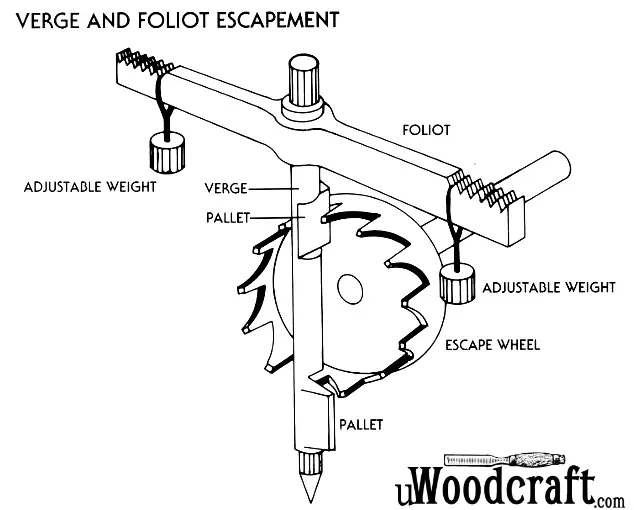
But even this action isn’t fully controlled and can fail to maintain the clock’s pace.
To keep this failure from happening, another device is added: the foliot.
The foliot is a cross-bar attached to the top of the verge.
Two small, adjustable weights hang from each end.
The escape wheel now has to oscillate both the verge and the foliot, which together serve as an additional check on its movement.
Even greater control is possible by moving the foliot weights.
This is done by hand. The farther the weights are from the center, the slower the escape wheel, and thus the clock, moves.
The closer the weights are to the center, the escape wheel, and thus the clock, speeds up.
How do Wind-up (Spring-Driven) Clocks Work?
Wind-up clocks utilize a spring for power. The spring is “wound-up” as a store of energy.
The unwinding of the spring is what powers the clockworks.
Horological Gears
Volumes of scholarly research have been devoted to horological gear theory, much of it quite mathematically complex.
Fortunately, most of this theoretical gobbledygook is not necessary for understanding how clocks work. All we need to understand the basics is some rudimentary algebra and high school physics.
Gear Basics
The concepts behind gearing is basic physics, so like any good physics example we will start by considering the theoretically “perfect” gears– two toothless disks like these.
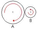
Our perfect gears touch at a single point, and never slip. The rotation of one gear is perfectly transmitted to the other. There is no friction between the gears themselves, and the pivots ride in frictionless bushings.
Unfortunately, ours is not a perfect world. If the gears are not held together very tightly, they will slip.
If they are held together tight enough so they will not slip there will be a lot of friction, which means more power will be required to drive the gears.
So how do we prevent the disks from slipping, without unduly increasing the friction?
Cut some teeth in the disks, so that they will engage each other! Voila! Gears!
Gear Teeth
Much of the scholarly research into gearing revolves around figuring out the ideal shape for gear teeth. With the right tooth profile, we can come close to the theoretically perfect gear described above.
The trick is to design the teeth so that their faces of the teeth will “roll” across each other, minimizing the sliding friction.
There are two types of curves commonly used in clock wheel teeth: epicycloidal (the curve generated by tracing a single point on a circle as it rolls) and involute (the curve generated by “unwinding” a line from a circle).
There’s actually a lot of very interesting math behind these shapes, but I’ll refer the interested readers to the bibliography below.
Commercial wheel and pinion cutters are available in different sizes, rated by their Module number. The Module of a cutter determines the pitch circle diameter (PCD) needed for a wheel with a specific number of teeth.
The PCD is the point at which the meshing gears actually touch, and is the same as the diameter of the theoretically perfect gear.
The actual outside diameter (OD) of the gear is larger than the PCD by a small amount.
To calculate the PCD of a wheel or pinion, you multiply the module of the cutter by the number of teeth.
For example, if you are using a module 1.0 cutter, a 48 tooth wheel would have a PCD of 48 mm. Using a module .8 cutter, the same wheel would have a PCD of 38.4 mm.
Calculating the OD of the wheel or pinion is a little trickier. Each tooth extends a small amount beyond the PCD, and this amount is directly proportional to the module.
For wheels the proportion is 1.38M, while for pinions it is .855M. We need to add twice this amount to the PCD to get the OD.
Thus we have the following equations for wheel and pinion sizes (M is module and n is # of teeth):
PCD = M * n
OD (wheels) = M * (2.74 + n)
OD (pinions) = M * (1.71 + n)
Gear Ratio
Let’s get back to the original gear diagram, again shown below.
Note that as disk A rotates clockwise (as shown by the red arrow), the fact that the disks are touching means that disk B will rotate in the opposite direction.
Note further that since the circumferences of the circle are in contact, if a point on the circumference of disk A moves a certain distance, a point on the circumference of disk B will move the same distance.
Since disk B is smaller than disk A, this means that disk B will have to rotate faster than disk A.
With a bit of math, you can show that the relative speeds of the two disks is proportional to their radii– This is called the gear ratio.
For example, if disk A is 100mm in diameter and disk B is 50mm, the gear ratio will be 2:1– B will rotate twice for every rotation of A.
This same formula can be applied to trains of gears– if we were to add a 10mm gear to the end of the train, we would end up with a 10:1 gear ratio (2:1 times 5:1).
If we throw pinions into the mix, things get even more interesting. Pinions ride on the same pivot as the wheel, so therefore they turn at the same speed as the wheel.
Since the pinions are much smaller than the wheels that they are driving, they can be used to effect dramatic speed increases.
Consider this typical gear train:
- Wheel 1: 80 teeth
- Pinion 2: 10 teeth, Wheel 2: 60 teeth
- Pinion 3: 10 teeth
Wheel 1 drives pinion 2 at an 8:1 ratio.
Wheel 2 and pinion 2 are on the same pivot, so pinion 2 is also at an 8:1 gear ratio.
Wheel 2 drives pinion 3 at a 6:1 ratio, we end up with a 48:1 gear ratio for the train!
In general, the gear ratio for a train of n gear/pinion pairs can be calculated as:
(W1 * W2 * ... * Wn-1) / (P2 * P3 * ...* Pn)
Note that the first pinion and last wheel do not show up in the equation– they do not have any bearing on the gear ratio, since they do not mesh with another gear.
The Escapement
The Escapement is the end of the clock’s gear train, and perhaps most important component of the train.
The job of the escapement is to precisely control the speed at which the train turns, thus allowing the train to keep accurate time.
Escapements come in a bewildering number of varieties– some suitable for tower clocks, others for pocket watches, but those commonly encountered in wall and shelf clocks all share the same basic structure: there is an escape wheel, whose specially-shaped teeth engage a pair of pallets that move back and forth with the pendulum.
The pallets are mounted on (or part of) an oscillating arm called the anchor, which is attached to the pendulum.
The escapement controls the speed of the train by “counting” beats of the pendulum.
When the pendulum swings all the way to one side, the pallet on one side releases a tooth, and the other pallet catches the next tooth in line.
When the pendulum swings to the other side, the process is reversed.
The pallets are normally arranged such that each back and forth beat of the pendulum moves the escape wheel forward one tooth.
The Escapement also plays one more very important role– it provides a small impulse to the pendulum, which allows the pendulum to overcome friction and keep moving.
Without this “push”, the pendulum would stop after just a few beats.
There are three particular types of escapements that account for a vast majority of the clocks made:
Recoil Escapement
The Recoil escapement is so named because at the very end of the pendulum’s arc, the escape wheel actually moves backwards a tiny amount.
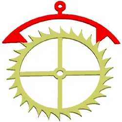
Recoil escapements are adequate timekeepers, and have the distinct advantage that they are somewhat “forgiving” of errors in construction or alignment of the pallets.
They were commonly used on low-cost clocks, and are popular amongst modern clockmakers.
Many modern clocks use a variation of the recoil escapement, where instead of a solid anchor a bent strip of metal is used.
These anchors are slightly less accurate than the solid, but much easier to adjust.
Dead-Beat Escapement
The Dead-Beat escapement is so named because the escape wheel stands perfectly still while the pallet is engaged– it moves forward only, with no recoil.
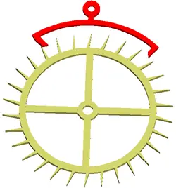
Dead-Beat escapements keep very accurate time, but are extremely “fussy” and difficult to make.
This type of escapement was typically used in only the best-quality clocks and chronometers.
The anchor in a dead-beat escapement requires very high tolerances for accuracy, and the pallets are subject to much more wear than those in a recoil escapement.
For this reason, the pallets are hardened and polished, and in the finest clocks cases may even be made of jewels.
Verge Escapement
The Verge escapement is very unusual in that it uses a horizontally-mounted escape wheel.
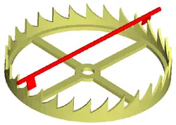
The anchor for a verge is simply a wire with two “flags” attached to it that act as pallets.
The anchor wire is typically the pivot for the pendulum, so this is a very mechanically simple escapement.
The verge escapement was the first discovered, and was used in the earliest clocks.
It has a couple of major disadvantages, though: it is not a particularly good timekeeper, and the fact that it requires a contrate wheel makes the mechanical linkage of the escape wheel somewhat complicated.
One interesting variant of the verge that turns up occasionally is the “recoil verge”.
Here, the verge wheel is cut with teeth like a recoil escapement, and a traditional recoil anchor is used.
These are very visually interesting escapements, and so are most often used in fancy skeleton clocks.
The Pendulum
Using the regularity of a pendulum’s swing as a timekeeper is an ancient idea.
Even before the principles of gravity explained why a pendulum beats evenly, the pendulum was used as an accurate timing device.
Pendulums in modern clocks consist of a weighted disk called a bob, mounted on the end of a shaft.
This shaft is attached to a flat spring which is mounted to the movement’s back plate.
The movement of the pendulum is transferred to the escapement anchor by means of an arm that straddles the pendulum rod, called the crutch.
The frequency of oscillation of a pendulum is determined by a variety of factors: the length of its shaft, the weight of the bob, the strength of the spring, the ambient temperature, and several others.
There is no way that we could come up with an equation to handle all of the various parameters, so again we turn to the physicist’s dodge of assuming a “perfect” abstract pendulum.
Our perfect pendulum is small weight attached to a weightless shaft that rotates about a frictionless pivot point in a vacuum.
The shaft is made of a material that does not bend, stretch, or change in dimension with temperature. In other words, it is nothing like a real pendulum… 😉
Newton’s laws of Physics tell us that our perfect pendulum will oscillate according to the following equation:
T = pi * SQRT(L/g)
Where T is the number of seconds to do a single swing of the pendulum, L is the length of the shaft, and g is the gravitational constant (9.814 meters per second per second).
Since T is determined by the train of the movement we need to solve for L, so a little algebraic magic yields:
L = g(T/pi)^2
This equation tells us that the “seconds pendulum” (a pendulum that beats once per second) should be 994.3 mm (39.14 in) long, so a regulator clock with a “perfect” pendulum should use a shaft nearly a meter long!
Once again, however, the real world does not fit our “perfect” world.
In the real world, most regulator clocks use a pendulum significantly shorter than the theoretical length and still beat perfect seconds, while smaller clocks often use pendulums much longer than the theoretical pendulum.
So the question now becomes: What good is this theoretical length?
In general, it is a good starting point for pendulum length, and not much else.
When fitting a pendulum, it will be mainly trial and error.
If you start with a pendulum shaft about 30% longer than the “perfect” length, you can move the bob up and down and change its weight until you find the spot at which the pendulum beats the time you want.
Once you have established the approximate position of the bob, you can cut the shaft and thread it for a rating nut to allow fine adjustment.
The Timekeeping (Going) Train
The heart of the clock is the Timekeeping train (sometimes referred to as the “Going” train).
It converts the power provided by the Power train into a precise rotation of the minute hand.
The Timekeeping train revolves around the center wheel.
This is usually the largest wheel in the clock, and in almost all cases will rotate exactly once per hour.
The center wheel is also the only wheel in the clock that has two pinions attached to it: the center pinion, which transfers the power of the Power train to the Timekeeping train, and the cannon pinion, which drives the Motion train.
At the other end of the Timekeeping train is the escapement.
The escapement controls the speed of the train by releasing the escape wheel with each swing of the pendulum– the faster the pendulum beats, the faster the escape wheel turns.
With careful selection of gears and pendulum length, we can precisely control the rate of rotation of the center wheel.
The gear ratio calculation for this gear sequence will give us the number of swings of the pendulum that will result in the center wheel making one rotation.
Since we know the center wheel rotates once per hour, it is also the number of beats per hour. This value is called the train of the clock. To calculate the train, we use the following equation:
train = (C*E*2)/e
Where C and E are the number of teeth in the center and escape wheels, and e is the number of teeth in the escape pinion.
The 2 in the equation comes from the escapement pallets– these act as a simple gear with 2 teeth.
If we plug some numbers into this equation, however, we are in for a bit of a surprise.
Considering a 1-second pendulum (3600 beats/hr) and a typical escape wheel and pinion of 30 and 6 teeth respectively, we would need a center wheel with 360 teeth!
Using a Module 1.0 cutter, this would mean a 36 cm wheel, which is obviously untenable.
To make the wheel sizes more reasonable, another wheel and pinion is added to the train.
This extra wheel (called the third wheel) gives us the following train calculation:
train = (C*T*E*2)/(t*e)
Where T and t are the number of teeth in the third wheel and pinion.
This equation gives us much more reasonable gear sizes.
For instance, assuming the same 1-second pendulum we can use the following gears:
Center Wheel: 64
Third Wheel/Pinion: 60 / 8
Escape Wheel/Pinion: 30 / 8
(64*60*30*2)/(8*8) = 3600
The Power Train
The Power Train is the sequence of gears that transfers the power of a weight or wound spring to the Timekeeping Train.
Power trains can be as simple as single gear connected directly to the power source, or a complex series of gears.
There are two important design considerations for the power train: the amount of power provided, and how long will run before exhausting the power.
Note that these two parameters are in opposition to each other– in order to increase the run time we need to increase the gear ratio, but the more we increase the gear ratio, the less power the train will provide for timekeeping.
In spring-driven clocks, the spring is typically held inside a covered tube called the barrel.
The barrel is attached to the gear with a ratchet, allowing it to be turned backwards for rewinding.
In weight driven clocks, the weight chain will either be wrapped around a barrel similar to the one used by the spring-driven clock, or run over a star gear that engages the links in the chain.
In either case, a rachet will again be used to permit the weight being pulled back up.
The limiting factor in how long the clock will run is how many times the spring can be wound for a spring-driven clock, or how far the weights can fall for a weight-driven clock.
As a rule of thumb, you can assume a fully wound spring will be able to rotate the barrel around 5 times.
In a weight-driven clock we have considerably more leeway.
In these clocks, the number of rotations of the barrel is determined by the following formula:
R = (L/pi*d)
Where L is the maximum length the weight can drop, and d is the diameter of the barrel.
We can achieve longer runs by increasing the length of the drop (like in grandfather clocks), or by increasing the diameter of the barrel.
Even with these clocks, though, 5 turns of the barrel is about average.
If we consider a typical 6:1 gear ratio for the single gear and pinion in a power train (let’s say a 48 tooth barrel and 8 tooth pinion on the center wheel), then we would get 30 turns of the center wheel on a single winding of the mainspring.
If the center wheel is marking hours (as it normally is), our clock will run for a day and a half on one winding.
This single-gear setup was common on smaller clocks and lower-cost clocks in the past, and is still in use for some low-end cuckoo clocks to this day.
To allow the clock to run more than a day on a winding, a second wheel and pinion is added to the train.
If we added another 6:1 wheel/pinion it would yield a 36:1 gear ratio, giving us 180 hours (7.5 days) on a single winding.
This setup was used on most larger clocks in the past, and is used almost exclusively today.
Clocks which use this type of train are called “8-day” clocks, and the extra wheel is typically called the 8-day wheel.
Some very fancy clocks will use even higher gear ratios to run longer on a single winding, but these clocks must make some accommodations for the loss of power due to the high gear ratio.
This means either increasing the power (by using heavier weights or more powerful springs), or decreasing the friction in the movement (by using jeweled pivot points).
The Motion Train
The last and simplest of the trains is the motion train.
The purpose of this train is to convert twelve turns of the cannon pinion (which drives the minute hand) into one turn of the hour hand.
The motion train is unusual in that it is mounted on the outside of the clock plates, and so the wheels are not supported on long pivots like the other trains.
The center wheel pivot extends through the clock plate slightly, and the cannon shaft and pinion is attached to this.
The cannon shaft is a bar with the cannon pinion riveted to it.
It is held in place on the center wheel pivot by a friction spring, which allows the shaft to turn without moving the center wheel (handy for setting the clock).
The far end of the cannon shaft is filed square to fit the minute hand bushing.
The cannon pinion is very different than the other pinions.
While it is technically a pinion, it looks very different from the other pinions in the clock.
It has a fairly large diameter and a large number of teeth, making it look much like a small wheel.
The cannon pinion drives the minute wheel and pinion, which in turn drive the hour wheel.
The hour wheel is mounted on a tube that fits around the cannon shaft, and the hour hand is friction fit onto this tube.
In order to make the hour hand rotate once for every twelve rotations of the minute hand, we need a 12:1 gear ratio for the motion train.
Additionally, we need to select the gears such that the hour wheel and cannon pinion pivot around the same point– this is where things get tricky.
In order to get our cannon pinion and hour wheel to rotate about the same point, we need to make sure that the radius of the cannon pinion plus the minute wheel is the same as the radius of the minute pinion plus the hour wheel.
Since we will make all of the gears using the same Module (we want them to mesh smoothly, after all), we can use the following equation:
(c+M) = (m+H)
Where M and H are the number of teeth in the minute and hour wheel, and c and m are the number of teeth in the cannon and minute pinion.
We also know that we need a 12:1 gear ratio, so we can also define the following equation:
(M*H)/(c*m) = 12
You’ll note we have 4 variables, but only 2 equations.
We could pick numbers randomly until we found some that worked, but a better way would be to invent some new constraints.
An easy constraint is to fix the ratio between the cannon pinion and minute wheel.
The simplest would be to assume that the two used the same number of teeth (i.e. 1:1 ratio), but any ratio could be used.
So let’s try an example.
If we assume a 1:1 ratio between the minute wheel and cannon pinion, we can simplify as follows:
c = M
(c+M) = (m+H) => H = 2M-m
(M*H)/(c*m) = 12 => H = 12m
Which leaves us with:M = 13m/2
Since commercial pinion cutters are designed to cut a certain number of teeth, it would be a great help to use the same number of teeth in the minute pinion as is used elsewhere in the movement– that way we would only need one pinion cutter.
If we were using a 6-tooth pinion, then, our numbers would be:
Cannon Pinion: 39
Minute Wheel 39
Minute Pinion: 6
Hour Wheel: 72
These wheels are large, but not out of the question.
If we were to use a 2:1 ratio, the results are even better:
c = M/2
(c+M) = (m+H) => H = (3M/2)-m
(M*H)/(c*m) = 12 => H = 6m
Which leaves us with:M = 14m/3
If we were to use the same 6-tooth pinion, our numbers wound be:
Cannon Pinion: 14
Minute Wheel 28
Minute Pinion: 6
Hour Wheel: 36
This is a nice simple train, and one commonly encountered in commercial clocks.
Bibliography
- Davis, Wilfred: Gears for Small Mechanisms. N.A.G. Press, London 1953.
The ultimate reference on horological gearing. It is not for the faint of heart (it reads like a mechanical engineering textbook), but it contains the best description of gear tooth mathematics and gear theory that I have encountered.
- DeCarle, Donald: Practical Clock Repairing. N.A.G. Press, London 1952.
Perhaps the finest general treatment of clockmaking and repair available. The book is very easy to read, profusely illustrated, and above all, practical. If you can get only one book on horology, this should be the one.
- Goodrich, Ward: The Watchmaker’s Lathe. North American Watch, Tool, and Supply Co., Fox River Grove, IL, 1952.
This is a reprint of a 1904 book covering the WW-style lathe and its myriad attachments. It covers all aspects of horological lathe work, in excruciating detail. Covers everything from setup and basic turning to screw-cutting and damaskeening.
- Haswell, J. Eric: Horology; The Science of Time Measurement and the Construction of Clocks, Watches and Chronometers. Chapman and Hall, Ltd., London, 1928.
A good basic primer for horology, which covers chronometers as well as clocks and watches. The section on escapements is very good, and covers some odd escapements that I have not found elsewhere.
- Hood, Grant: Modern Methods of Horology; A Book of Practical Information for Young Watchmakers. Kansas City Jeweler and Optician, Kansas City MO, 1904.
A very nice collection of articles from a turn-of-the-century trade magazine. Covers a wide range of topics (mainly in watchmaking). Quality of the articles varies, but most are quite good.
- Levin, Louis and Levin, Samuel: Practical Benchwork for Horologists. L. Levin & Son, Los Angeles CA, 1946.
A good “working-man’s” guide to horology, from the president of a instrument lathe manufacturing company. Not a lot of technical information here, but a great description of the basic horological tools and how to use them.
- Rawlings, Arthur: The Science of Clocks and Watches. Pitman Publishing Corp., New York NY, 1948.
An outstanding textbook covering the mathematics and physical principles of horology. You will need a basic understanding of physics and algebra to understand some of the sections, but it is surprisingly easy to read and quite thorough.
- Saunier, Claudius: Treatise on Modern Horology in Theory and Practice. Translated by Tripplen, Julien. C. T. Branford Co., Newton Center, MA, 1975
An English translation of the master work of one of the pioneers in Swiss watchmaking. The prose is somewhat encyclopedic (typical of 19th century technical books) and a little tough to get used to, but it covers a lot of material. Most of what’s here is covered elsewhere, though.
- Thorne, C.J.: Clockmaking for the Home Shop Machinist. Guy Lautard, Publisher, Vancouver, BC, 1997.
This is a wonderful “how-to” book for clockmaking, aimed at the amateur machinist.